If you already model with a timeline, Combine, and user parameters, you already know this editor: the Objects tree is the timeline, Combine's Join, Cut, and Intersect are the union, difference, and intersection choices on one Boolean node, and the Fx parameter table is the Variables panel.
Those habits are the same in Rig Cad. A bracket or a tray is a valid first project here. You do not park the simple version in another tool.
What you will learn: where the Fusion browser, timeline, Combine, and Fx table map; how Join / Cut / Intersect appear in the Objects tree; a mounting tab driven like user parameters; and a tray sized from measurements.
If the editor is new, keep Rig Cad Editor Guide: The Five Core Panels open in another tab.
If you already think in features and parameters
Fusion records a recipe: sketches, features, and named parameters. Rig Cad records a recipe too. The tree is the history. Variables are the Fx table.
The habits you already have are enough to start:
- Combine Join / Cut / Intersect → union / difference / intersection
- a user parameter → a Variable
- a feature that should update when a parameter changes → a node that reads that Variable
- a one-off body with typed sizes → literals in Properties
Build the simple part here. Add names when a hole, wall, or fillet should track another measurement.
Where it lives in the editor
Table: Fusion 360 UI next to Rig Cad panels.
| In Fusion 360 | In Rig Cad |
|---|---|
| Browser (bodies, components) | Objects tree |
| Timeline | The same tree. Operations stay editable. |
| Create / Solid primitives | Add Object |
| Sketch + Extrude / Revolve | Profiles, then a solid stage. Keep them separate; see Sketches to Solids. |
| Combine Join / Cut / Intersect | Union, difference, intersection on the selected operation |
| Modify → Change Parameters (Fx) | Variables; the grammar is in Expressions and Variables |
| Inspector / feature dialog | Properties |
| Rectangular / circular pattern | Linear and Radial Repeat; see Repeats and Arrays |
| Shell, mirror, section | Post-Processing: Shell, Mirror, Cut Plane, Surface Offset |
| Fillet or chamfer where two bodies meet | SDF Mode on the Boolean, then a Smooth width with the Circular (fillet) or Chamfer Blend Mode; the five routes are in Fillets and Chamfers |
| Thread feature | The Thread node; see Threads and Snap Fits |
| Component origin, joint origin | A parent node's frame; see Transforms and Reference Frames |
| Export mesh | Download from the project or the embed; see Export for the Slicer |
You can ignore Variables on a first part. Type literals in Properties the way you type sizes into a feature dialog.
Combine is the Objects tree
Fusion's Combine tool is union, difference, and intersection. Rig Cad writes that sentence as a parent in the Objects tree. Child order matters the same way Target / Tool does: the first child of a difference is the body you keep.
Table: Combine next to Rig Cad operations.
| Fusion Combine | Rig Cad operation | What it records |
|---|---|---|
| Join |  Union Union |
Keep volume inside any child |
| Cut |  Difference Difference |
Keep the first child; remove the rest |
| Intersect |  Intersection Intersection |
Keep only the shared volume |
| (no Combine equivalent) | 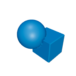 Symmetric difference Symmetric difference |
Keep what is in one body but not both |
| (no Combine equivalent) |  Hull Hull |
Convex envelope around the children |
Switch the operation on the same two solids. The recipe stays on the timeline. Here the timeline is the tree.
User parameters are Variables
In Fusion you open Modify → Change Parameters and write thickness and hole_d. Features read those names. That is already how Rig Cad works.
partThickness   = 8
holeDiameter    = 10
cutterOvershoot = 2
cutterDepth     = partThickness + 2 * cutterOvershoot
partThickness and holeDiameter are user parameters. cutterDepth is an expression, the same class as a Fusion driven dimension. The hole stays a through-hole when thickness changes.
A one-off tab does not need this table. Type 8 and 10 in Properties. Name them when the second size has to stay a through-hole.
A configured tray is still a Combine
Outer body, inner cavity, patterned dividers. In Fusion that is Combine Cut plus a pattern. Here it is a difference, a union, and a repeat.
User-facing parameters: trayWidth, trayDepth, trayHeight, wallThickness, compartmentCount, cornerRadius. Divider count and spacing are expressions.
Try wallThickness at 1.6 mm and look at the floor. That check belongs on the parameters, the same way you would put a minimum on a Fusion user parameter.
What maps, and what you can add
Table: Fusion habits next to Rig Cad.
| Task | Fusion habit | In Rig Cad |
|---|---|---|
| First solid | Sketch, extrude, or a primitive. | Primitive or profile, then the tree. |
| One-off part | Typed sizes in a feature. | Typed sizes in Properties. |
| Same part, new size | Edit a user parameter. | Edit a Variable. |
| History | Timeline. | Objects tree. |
| Sharing | An f3d, or a mesh. | A project, a mesh, or a configurator. |
Next
The operations are already familiar. Constructive Solid Geometry in Rig Cad is how to write the tree so it stays editable.
If a cut leaves a cap after a move, Oversize the Cutter is the through-all habit, written as an expression. Shell and mirror are in Post-Processing. Component and joint origins are parent frames; Transforms and Reference Frames is that article. Beyond Sliders is for constrained families.
Arriving from a different tool? The same map exists for Tinkercad, OpenSCAD, Onshape and SolidWorks, and Blender Geometry Nodes.
Comments
Loading comments...