A box, a cylinder, and a hole are not a part until you define how they combine. In Rig Cad, constructive solid geometry (CSG) records that recipe: union the base and rounded end, then subtract the cutter. The operation tree keeps those decisions, so changing a dimension regenerates the part instead of leaving only a final surface.
The Objects panel displays this scene tree. It is the sentence that states what geometry is kept, joined, or removed. If the interface is unfamiliar, begin with Rig Cad Editor Guide: The Five Core Panels.
What you will learn: how to read a CSG tree; how union, difference, intersection, symmetric difference, and hull combine shapes; and how to build a first part that remains editable.
What constructive solid geometry means
CSG describes a solid as a combination of primitives—boxes, cylinders, spheres, capsules, tori, and other shapes with controllable dimensions—and operation nodes.
A simple mounting tab can be written as:
difference(union(base, roundedEnd), holeCutter)
Read this as: join the rectangular base and rounded end, then subtract the through-hole. The expression records design intent, so you can change the base width, rounded-end diameter, or hole size without rebuilding the model.
Boolean operations and hull
The core CSG operations are often called Booleans because they classify regions of space as retained or removed. Select an operation node in the object tree, then choose the relationship from the Operation selector in Properties. All five choices live on the same node, so a union can become a difference without rebuilding the tree.
Table: The five operation choices on a Boolean node.
| Operation | Result | Common uses |
|---|---|---|
 Union Union |
Retains the volume inside any child | Join a base, ribs, bosses, handles, or supports |
 Difference Difference |
Keeps the first child and removes the remaining children | Make holes, slots, pockets, vents, and hollow interiors |
 Intersection Intersection |
Keeps only the volume shared by every child | Trim a form, isolate an overlap, or create a bounded fragment |
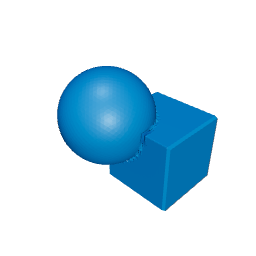 Symmetric difference Symmetric difference |
For two inputs, keeps the volume belonging to one input but not both | Exclusive leftovers, interlocking cutouts, and overlap comparisons |
 Hull Hull |
Creates the convex envelope around every child | Convex bridges, blended supports, and simple envelopes |
A union does not guarantee one connected body. Geometry that should become one part must overlap; disjoint children can remain separate volumes.
Difference is ordered: its first child is the base, and every later child is a cutter.
difference(panel, hole, slot) means “keep the panel, then remove the hole and slot.” Reversing the panel and hole produces a different result. When a difference produces nothing or removes the wrong region, check child order before changing dimensions.
Symmetric difference is the exclusive leftover. Rig Cad exposes it directly as an operation choice. For two inputs, it is mathematically equivalent to:
difference(union(A, B), intersection(A, B))
Hull is grouped with the primary operations because it is useful for bridges and envelopes, but it is not a Boolean. It wraps its children in the smallest convex solid that contains them, so it fills concavities and closes holes that lie inside that envelope.
Read the scene tree as a geometric sentence
In Rig Cad, the scene tree is not just an object list. Parent-child relationships define how geometry is evaluated. In the editor, that sentence is the object tree.
Diagram: The finished mounting tab is a difference containing a union body made from a base box and rounded-end cylinder, with a hole cylinder subtracted.
flowchart TD
  R["Difference: Finished Mounting Tab"] --> U["Union: Body Union"]
  R --> H["Cylinder: Hole Cutter"]
  U --> B["Box: Base"]
  U --> S["Cylinder: Rounded End"]
These are the node names in the embedded CSG Mounting Tab Demo, so the diagram and the Objects panel read the same way. Read from the leaves upward. The box and rounded end become one body under the union. The hole cylinder is then subtracted by the difference. Selecting a leaf shows its dimensions and transform; selecting an operation shows the relationship between its children.
Names make this much easier to debug. “Box 1” and “Cylinder 2” describe implementation accidents. “Base,” “Rounded End,” and “Hole Cutter” describe why the nodes exist.
One constraint rides along with that. Expressions reach a node through its name, and the parser treats a space as the end of one symbol and the start of another: Hole Cutter.radius is read as Hole and Cutter.radius, and neither resolves. Spaces are fine for nodes you only ever select by hand, but give any node you intend to reference from an expression a single-token name — HoleCutter or Hole_Cutter. Expressions and Variables in Rig Cad has the full grammar.
The object tree makes the recipe visible in the editor. Select a node to highlight it in the viewport. Changing the operator on a selected Boolean recomputes the result automatically. Drag a node to a new parent when the recipe needs a different order.
A mounting tab, one decision at a time
Plan the first part before you add nodes.
- What is the solid? A box and a cylinder. They belong together, so place them under a parent union.
- What is the cutter? A narrower cylinder for the through-hole. It does not live inside the union. It is a sibling under the difference.
- When do you subtract? After the body is one piece. If you cut the hole from the cylinder first, then union it with the box, the hole only goes through the rounded end.
In the object tree, the first child of a difference is the base. Later children are cutters. You can change the operator after the nodes are in place.
Coordinates describe both size and placement
Rig Cad uses +Z as world up, the XY plane as the base plane, degrees for rotations, and millimetres for every length. Every node also has its own local coordinate system.
For an unrotated box, width follows local X, height follows local Y, and depth follows local Z. A box that should be 6 mm thick vertically therefore has a depth of 6 mm. Follow the node’s documented local axes, then rotate only when the geometry needs a different orientation.
In the properties panel, those values are the node’s transform:
- dimensions define the shape in local space;
- position places its origin relative to its parent;
- rotation redirects its local axes; and
- scale multiplies the local result.
A rotated cutter’s “through” direction rotates with it. Lengthen the cutter along its local cutting direction before relying on world-space bounds. Transforms and Reference Frames in Rig Cad covers frames in more depth.
Groups create movable features
A reusable mounting feature may contain positive geometry, such as a boss, and negative geometry, such as its coaxial cutter. Build the feature near a sensible local origin, place its pieces relative to one another, and move the enclosing group. In the object tree, that group is just a parent you can select and move.
This keeps local dimensions readable and lets the whole feature move, rotate, or scale as one assembly. Pattern the complete mounting feature instead of patterning the boss and cutter separately.
A CSG tree becomes parametric when inputs have names
Literal dimensions are enough to prove a construction. Named variables turn it into a reusable design.
partThickness   = 8
holeDiameter    = 10
cutterOvershoot = 2
cutterDepth     = partThickness + 2 * cutterOvershoot
These are the variables in the embedded demo; roundedEndCenterX = baseLength / 2 and roundedEndRadius = tabWidth / 2 are its other derived helpers, and they keep the rounded end and the hole coaxial when the base length changes.
The user-facing values describe meaningful choices. Derived expressions record the relationships required to keep the construction valid. When partThickness changes, the cutter depth changes with it, the difference recomputes, and the through-hole remains a through-hole.
Expose only meaningful decisions in the configurator. Internal helpers such as cutterDepth should usually remain derived and hidden. The formula language, the variable types, and the readouts and validators that go with them are documented in Expressions and Variables in Rig Cad; Beyond Sliders: Designing Safe Parameter Spaces for Printable Products develops this idea into a complete system of ranges, dependencies, and validation rules.
2D profiles and 3D solids
Rig Cad can apply Boolean operations to either 2D regions or 3D solids, but the two stages should not be mixed in one operation.
For a plate-like part, combine compatible closed profiles and then extrude once:
difference(outerProfile, holeProfiles) → extrude
For geometry that is already solid, use a solid cutter:
difference(solidPlate, solidCutter)
Keep the stage explicit: profile operations before extrusion, solid operations after. Once a 3D solid is present, profile children cannot define solid regions in that Boolean. Sketches to Solids covers the profile stage in full: drawing an outline three ways, the 2D Booleans and repeats, and the extrude, revolve, and offset operations that turn it into a solid.
Robust construction uses clear overlap
Two surfaces that merely touch create an ambiguous boundary relationship. A through-hole cutter that ends exactly on the part’s entry and exit faces may look correct in one state but leave a cap, sheet, or fragment after a dimension or transform changes.
Extend temporary through-cutters beyond the retained solid:
cutterDepth = partThickness + 2 * cutterOvershoot
The extra length lies outside the finished part, so it does not change the useful hole depth. It simply turns surface coincidence into unmistakable volume overlap.
Keep this margin separate from physical clearance. Clearance changes how finished parts fit. Cutter overshoot changes only how reliably the intended topology is constructed. Oversize the Cutter: Reliable Boolean and SDF Modeling in Rig Cad covers transformed cutters, blind features, smoothing bands, and verification in depth.
Inspect the construction, not only the silhouette
A convincing viewport angle cannot prove every internal relationship. Use the editor as an inspection environment while the model is still easy to change.
- Give feature and cutter branches distinct colors so the tree matches the viewport.
- Hide or isolate a parent when you need to see its inputs.
- Make through-cutters overshoot the part so they do not share a face with the solid.
- Use a cross-section to check holes, walls, and leftover overlap.
Keep construction colors until the geometry is approved. Color is how a tree branch maps to the object you see.
Common CSG failures
Table: Common CSG symptoms, their likely causes, and the first thing to check.
| Symptom | Likely cause | First check |
|---|---|---|
| Difference produces nothing | The base and cutter are reversed, or the cutter completely contains the base | Check child order and containment |
| Difference appears unchanged | The cutter does not overlap the base | Check transforms and solved bounds |
| A hole leaves a cap | Cutter ends on an outer face | Extend it beyond both sides |
| A feature moves apart after resizing | Placement uses unrelated fixed coordinates | Derive placement from host dimensions |
| A rotated cutter misses the part | It was lengthened along the wrong axis | Inspect its local cutting direction |
| A profile is marked unused | 2D and 3D inputs were mixed | Separate profile and solid stages |
| Repeated pieces drift apart | Component parts were patterned separately | Repeat the enclosing feature |
| The default looks right but extremes fail | Inputs have ranges but no relational rules | Test boundary combinations |
The tree usually contains the explanation. Before adding complexity, ask whether every node has the correct role, parent, coordinate system, and overlap.
Mesh or SDF
CSG describes how shapes combine. It does not require one internal representation.
Rig Cad can solve the same tree with mesh operations for crisp manufactured features, or as a signed distance field (SDF) for smooth, field-defined geometry. Turn on SDF Mode on a Boolean—the purple diamond in the Objects tree—and that branch is evaluated as a field: the operation gains a Smooth blend width, a Blend Mode (rounded, chamfered, stepped, and others), and a Precision setting on the root of the branch. The same tree habits apply to both kernels: name the inputs, keep the recipe readable, and check the result.
For the field mathematics, precision, and mesh conversion, continue with Signed Distance Fields: Geometry as a Function. If you think in Blender's Geometry Nodes, Geometry Nodes, Displacement, and the Implicit Tree maps that graph onto this tree.
Next steps
CSG establishes the model’s structure. Continue with Transforms and Reference Frames in Rig Cad to place complete features without breaking their internal relationships. Then use Post-Processing in Rig Cad for ordered result-level operations and Mesh Cleanup in Rig Cad for final topology and polygon control.
For focused extensions, use Oversize the Cutter to make subtraction robust, Signed Distance Fields for smooth field-defined geometry, and Beyond Sliders for constrained product variables. The everyday building blocks that follow this tree each have their own article: Expressions and Variables, Sketches to Solids, Fillets and Chamfers, Shell, Hollowing, and Wall Thickness, Repeats and Arrays, and, when the part is done, Export for the Slicer.
Coming from another tool? The Getting Started guides map familiar habits onto this operation tree: Rig Cad for Tinkercad Users, Rig Cad for Fusion 360 Users, Rig Cad for OpenSCAD Users, Coming from Onshape or SolidWorks, and, for Blender users, Geometry Nodes, Displacement, and the Implicit Tree.
Comments
Loading comments...