Pattern 3D is one node that produces any of more than 150 periodic, stochastic and textured solids: gyroids and other minimal surfaces, strut lattices, foams, weaves, knurls, valves. Bound it with an Intersection and it becomes a lightweight core; feed the same families to the Infill and Surface Pattern steps and they become a skinned lattice or a grip texture on an existing part. This article covers the node, the families, the two field-only steps, and what prints.
One node, a box of pattern
Pattern 3D lives under Solids. It fills a box of width, height and depth with the chosen patternType, and its other options decide what the pattern is made of:
Table: Pattern 3D options that shape the result.
| Option | Meaning | Practical note |
|---|---|---|
scale |
Unit-cell scale factor; higher is coarser | The TPMS example uses 0.5 in a 20 mm box; the demo uses 0.6 in a 40 mm puck |
sheetMode |
sheet builds a double-walled shell on the iso-surface; solid fills one side of it |
Sheet for lattices and heat exchangers, solid for a split-space part |
thickness |
Wall thickness of the sheet | Two extrusion widths minimum for FDM |
solidSheetOperation |
In solid mode, add or subtract the thickened sheet | Makes a solid with a thickened skin on the surface |
invert |
Swap material and void inside the bounds | The complementary lattice |
seed |
Random seed for stochastic families | Voronoi, noise, foams |
unboundedSdf |
Continue the field beyond the box | Only meaningful under a bounding parent |
precision, decimation, sdfEngine |
Its own meshing controls | The node meshes itself; see the bounding section |
The node also accepts weighted point fields as children, which supply the sites for Voronoi-style modes, so a foam can follow points you scatter rather than a random seed. A pattern variable bound to patternType gives a configurator a picker with previews, which is what the demo exposes.
The families
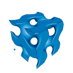
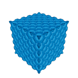
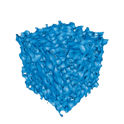
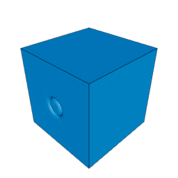
Table: Pattern families and representative types. The picker shows every type with a preview.
| Family | Examples | Typical use |
|---|---|---|
| Triply periodic minimal surfaces | gyroid, schwarz_p, schwarz_d, neovius, iwp, fks, lidinoid, double_gyroid |
Lightweight cores, heat exchangers, self-supporting infill |
| Strut lattices | octet, isogrid, kagome, bcc_z, fcc_z, diamond_lattice, woodpile, gyroid_struts |
Stiffness-to-weight, open cells that drain |
| Mechanical metamaterials | auxetic, auxetic_star, hexachiral, rotating_squares, pentamode, lattice_hinge, spiral_flexure |
Compliant and negative-Poisson parts |
| Foams and stochastic | voronoi, voronoi_struts, spinodal, plateau_foam, closed_cell_foam, noise, organic, brain_coral, turing |
Organic looks, energy absorption |
| Textiles | woven, chainmail, knitted, basket_weave, twill, satin, braid, rattan |
Decorative panels and flexible sheets |
| Functional forms | tesla_valve, static_mixer, bellows, helical_spring, screw_thread, herringbone, offset_strip_fin, qrd, fresnel, retroreflector |
Fluidic and optical inserts |
| Surface textures | straight_knurl, diamond_knurl, dimples, shark_skin, leather, hammered, sandpaper, stipple, wood_grain, diamond_plate |
Grip and finish; see Surface Pattern below |
| Fractal and mathematical | menger, mandelbulb, mandelbox, apollonian, sierpinski_octahedron, catenoid, helicoid, costa, quasicrystal |
Showpieces and teaching models |
| Origami and corrugation | miura, waterbomb, yoshizawa_corrugation, corrugated, egg_crate |
Stiffened panels |
The gyroid is the one to start with, and Gyroids: The TPMS Surfaces covers why it prints so well. The mathematics that turns any of these into a solid is in Signed Distance Fields.
Bounding a lattice, and the GPU caveat
A lattice is rarely wanted as a box. The companion puck bounds it with an Intersection and wraps it in a skin.
Diagram: The puck tree. A union joins a mesh-mode intersection of the Pattern 3D node with a bounding cylinder, and a difference of two cylinders that forms the optional skin.
flowchart TD
  U["Latticed_Puck (union)"] --> I["Lattice_Core (intersection, mesh mode)"]
  U --> S["Skin (difference, enabled = showSkin)"]
  I --> L["Lattice (Pattern 3D, meshes itself at meshPrecision)"]
  I --> B["Core_Bounds (cylinder, radius = coreRadius)"]
  S --> O["Skin_Outer (cylinder)"]
  S --> N["Skin_Inner (cylinder, radius - skinThickness)"]
The Pattern 3D node meshes itself with its own precision, and the Intersection is an ordinary mesh Boolean that trims that mesh to the cylinder. The TPMS example project is built the same way. The skin is a separate ring so the lattice reaches the wall and fuses with it, and coreRadius shrinks the core by the skin thickness only when the skin is on.
Scale, thickness, precision: three different numbers
scale sets how big a cell is, thickness sets how much material each wall carries, and precision sets how finely the result is sampled. They interact in cost and in printability.
Table: Measured on the 40 mm demo puck, gyroid, sheet mode, thickness 0.8.
| scale | precision | Triangles | Solve time |
|---|---|---|---|
| 0.6 | 0.75 | 291,974 | 1.4 s |
| 0.6 | 0.6 | 436,234 | 2.1 s |
| 0.6 | 0.35 | 1,228,926 | 5.7 s |
At a scale of 6 the puck came out solid, because the unit cell was larger than the part and the whole puck sat inside one material region. Scale is a factor, not a millimetre value; find the right one by looking. Precision should stay coarse until the geometry is approved, because a lattice's surface area is enormous and every halving of precision roughly quadruples the triangles. decimation at 0.6 trims the result further without moving the walls.
For FDM, thickness should be at least two extrusion widths, and the cell should be large enough that the slicer draws each wall as a wall rather than a filled gap: cells of 4 mm and up at a 0.4 mm nozzle. Sheet-mode TPMS surfaces are self-supporting because the surface never exceeds a moderate overhang; strut lattices need their struts above the printer's overhang limit or a process that does not care.
Infill and Surface Pattern: the field-only steps
Two post-processing steps apply the same families to an existing solid, and both run only on the SDF solver, so the node that owns them must be evaluated as a field.
Infill keeps an outer skin of shellThickness and fills the interior with a lattice: patternType, sheetMode, patternThickness, and an optional smoothUnion with a smoothness radius that fillets lattice to skin. It is the one-step version of the puck above, on any shape.
Surface Pattern embosses or debosses a family into a surface: depth, patternThickness, mode, and a smoothBlend with blendRadius. The texture families, knurls, dimples and shark skin, are what it is for; a gyroid also works as a decorative relief.
Both steps share the modulation controls: densityMode, thicknessMode and morph can be driven by a radial field, an image, or a point field, so a lattice can thicken toward a load path or morph from gyroid to diamond across a part. The Geometry Nodes article covers the field nodes those controls read.
Where to go next
The skin around a lattice is the wall-thickness problem of Shell, Hollowing, and Wall Thickness. A lattice that has to leave the browser as a file is the heaviest case in Export for the Slicer. And a pattern applied as texture to a sellable part is one of the option surcharges discussed in Pricing Customized 3D Prints.
Comments
Loading comments...